I. Overview
Dynamic Host Configuration Protocol (DHCP) has been widely adopted as a protocol for allocating network configuration data, including an IP address, dynamically to a client device (PC) inside operator networks and corporate networks over time. Despite such a wide use of the protocol over decades, only few fully understand its detailed operation. So, in this document, we will explain the detailed operation of DHCP through three different technical topics.
This document covers three technical topics about the detailed DHCP operations and is organized as follows: Chapter II will describe how a DHCP client with an allocated/leased IP address detects IP address conflicts through Address Resolution Protocol (ARP). Chapter III will describe how a DHCP Offer/Ack message is unicasted or broadcasted to a DHCP server depending on the Broadcast Flag of a DHCP Discover/Request message. Chapter IV will describe the state transition of a device (DHCP client) during IP address allocation /lease and IP address renewal procedures.
Before you read this document it is recommended that you refer to the companion document, “Understanding the Basic Operations of DHCP” [3].
II. Procedure for Detecting IP Address Conflicts
Once a device gets an IP address allocated by a DHCP server through the procedures (a) ~ (d) in Figure 1, it broadcasts an ARP Request packet (using the allocated IP address as a target IP address) on the same subnet to detect a client device which uses the same IP address as its own IP address, as shown in the procedure (e) of Figure 1. Then it waits for any ARP Reply packet to be sent in response to the ARP Request packet that it broadcasted. If there is an ARP Reply packet, it means there is a conflicting device on the subnet, and if not, it means no conflicting device.
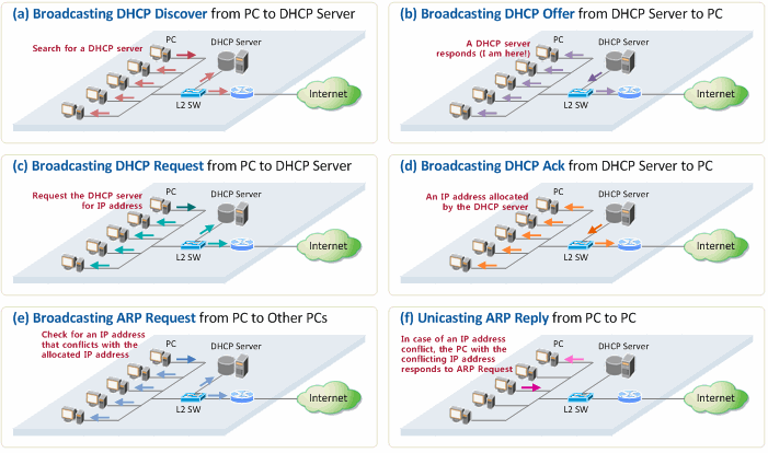
Figure 1. Procedure of IP address allocation and IP conflict detection
Figure 2 shows an ARP Request packet that is broadcasted from a PC (Windows 7) to detect an IP address conflict. Here, the message that the packet is conveying is “Please let me (00:17:42:c1:c8:f7) know if there is a device with the IP address (192.168.10.11)”.
Figure 2. ARP Request packet for detection of an IP address conflict
The procedure for sending an ARP Request packet is as follows:
- It is broadcasted to the entire subnet so that all the clients can receive the packet.
- The Sender MAC address field includes the MAC address of the client sending the packet (00:17:42:c1:c8:f7).
- The Sender IP address field includes a void address (0.0.0.0) instead of an address allocated to the client in order to prevent other devices/routers on the same subnet from updating their own ARP caches (because it has not been confirmed yet whether or not the device can use the IP address (192.168.10.11).
- The Target IP address field includes the client IP address allocated by the DHCP server. If there is any other client who is already using the same IP address, then it sends an ARP Reply packet in response to the ARP Request packet.
In general, no other client on the subnet has the same IP address as the client’s (unless the IP address has been set as a static IP address in a PC). Obviously, then the client receives no ARP Reply packet that responds to the ARP Request packet, and finally connects to the Internet using the IP address allocated by the DHCP server.
However, in case there is other client already using the same IP address as the client’s on the subnet, the other client which received the ARP Request packet responds by unicasting an ARP Reply packet, as shown in the procedure (f) of the Figure 1. That is to convey a message, “I’m using the IP address!” to the client (sender of the ARP Request packet). Figure 3 shows the information included in the ARP Reply packet.
Figure 3. ARP Reply packet sent by the conflicting client in case of an IP address conflict
The procedure for sending an ARP Reply packet is as follows:
- The client who received an ARP Request packet sends an ARP Reply packet that includes the source MAC address and the destination MAC address that are set as the MAC address of the ARP Reply packet sender and the MAC address of the ARP Request packet sender, respectively.
- The Sender MAC address and Sender IP address fields include the MAC address and the IP address of the ARP Reply sender, respectively.
- The Target MAC address field includes the MAC address of the ARP Reply packet receiver.
When the client becomes aware of the conflict of its IP address through these procedures, it notifies the DHCP server of the fact that the allocated IP address is already in use on the subnet by sending a DHCP Decline message to the server. Then, the client resumes another IP allocation procedure, broadcasting a DHCP Discover message again.
III. DHCP Offer/Ack Messages: Broadcast or Unicast?
According to our technical document, “Understanding the Basic Operations of DHCP” [3], all DHCP messages (including DHCP Offer/Ack) that are exchanged in the IP allocation procedure are broadcasted (Destination MAC=FF:FF:FF:FF:FF:FF, Destination IP=255.255.255.255) as shown in Table 1.
Table 1. Ethernet and IP address of DHCP messages

However, some DHCP-related documents provide different explanations for the transfer mode of DHCP Offer/Ack messages, causing confusion.
Hence, to have a more clear understanding, we configured a network environment in which Wireshark (http://www.wireshark.org/) is installed at a PC (Windows 7) as shown in Figure 1. Then, we captured DHCP messages to see if the messages are broadcasted or unicasted using the capture program, and analyzed the captured messages to find out what makes them unicast or broadcast.
For this, we had the PC get an IP address by entering “ipconfig /release” and “ipconfig /renew” in the DOS command window.
DHCP Discover message
Figure 4 shows the DHCP Discover message sent by the PC (Windows 7) to the DHCP server.
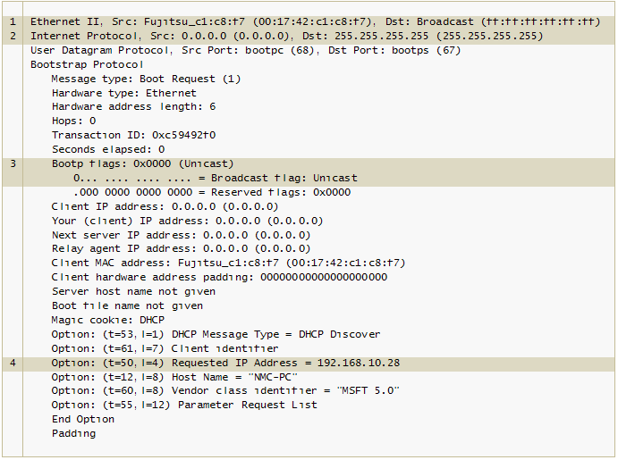
Figure 4. DHCP Discover message
Here, the PC:
- broadcasted a DHCP Discover message on the Ethernet, with the source MAC address and the destination MAC address set as the PC MAC address and FF:FF:FF:FF:FF:FF, respectively.
- broadcasted a DHCP Discover message on the subnet, with the source IP address and the destination IP address set as 0.0.0.0 and 255.255.255.255, respectively.
- set “Broadcast Flag” in the message to 0 in order to let the DHCP server which would receive and respond to the DHCP Discover message know that the PC would like to receive a DHCP Offer message through unicast.
- sent a DHCP Discover message along with its allocated IP address (192.168.10.28) that it had kept in it (Windows 7 registry), in order to convey a message, “I would like to receive the same IP address, 192.168.10.28” to the DHCP server.
DHCP Offer message
Figure 5 shows the DHCP Offer message sent by the DHCP server to the DHCP client (Windows 7) in response to the DHCP Discover message.
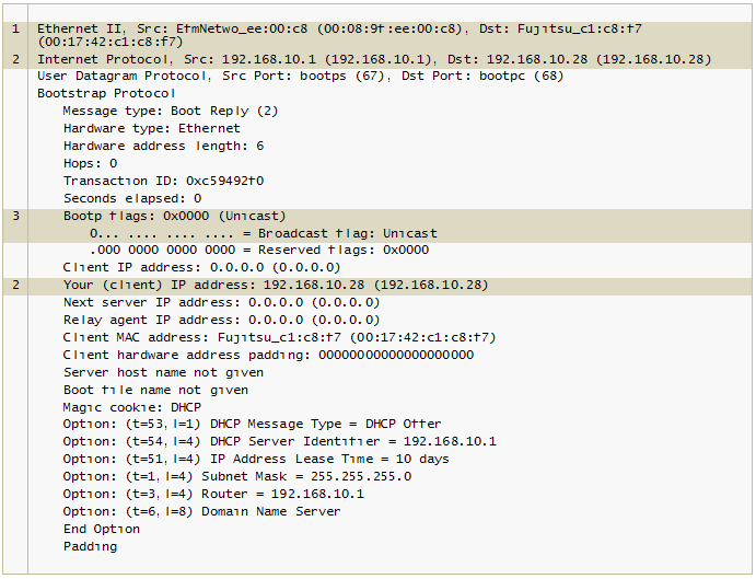
Figure 5. DHCP Offer message
Here, the DHCP server:
- unicasted a message on the Ethernet, with the source MAC address and the destination MAC address that are set as the DHCP server MAC address and the PC MAC address, respectively. This had a result different from the one in Table 1 (where the destination IP address was a Broadcast address) because of the Broadcast Flag value of the DHCP Discover message. In other words, if the Broadcast Flag value of a DHCP Discover message is set to 0 (representing a Unicast mode), a DHCP server definitely unicasts the DHCP Offer message.
- unicasted a message on the IP subnet, with the source IP address and the destination IP address that are set as the DHCP server IP address and the Your IP Address=192.168.10.28, respectively. Again, this had a result different from the one in Table 1 (where the destination IP address was a Broadcast address) because of the Broadcast Flag value of the DHCP Discover message. In other words, if the Broadcast Flag value of a DHCP Discover message is set to 0 (representing a Unicast mode), a DHCP server definitely unicasts a DHCP Offer message.
- copied the Broadcast Flag value of the DHCP Discover message, pasted it into the corresponding field of a DHCP Offer message, and then sent it to the client.
DHCP Request message
Figure 6 shows the DHCP Request message from the DHCP client (Windows 7) to the DHCP server.
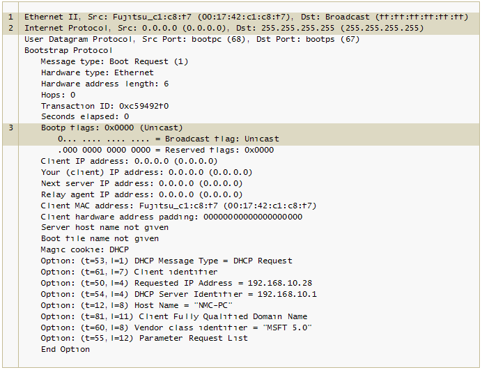
Figure 6. DHCP Request message
Here, the DHCP client:
- broadcasted a message on the Ethernet, with the source MAC address and the destination MAC address that are set as the PC MAC address and FF:FF:FF:FF:FF:FF, respectively.
- broadcasted a message on the IP subnet, with the source IP address and the destination IP address that are set as 0.0.0.0 and 255.255.255.255, respectively.
- set “Broadcast Flag” in the message to 0 in order to let the DHCP server which would receive and respond to the DHCP Request message know that it would like to receive a DHCP Ack message through unicast.
DHCP Ack message
Figure 7 shows the DHCP Ack message sent from the DHCP server to the DHCP client (Windows 7) in response to the DHCP Request message.
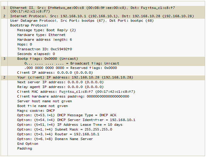
Figure 7. DHCP Ack message
Here, the DHCP server:
- unicasted a message on the Ethernet, with the source MAC address and the destination MAC address that are set as the DHCP server MAC address and the PC MAC address, respectively. The destination address was NOT set as a broadcast MAC address because the Broadcast Flag value of the DHCP Request message sent by the client is set to 0 (Unicast).
- unicasted a message on the IP subnet, with the source IP address and the destination IP address that are set as the DHCP server IP address and Your IP Address=192.168.10.28, respectively. Again as in MAC addresses, the destination address was NOT set as a broadcast IP address because the Broadcast Flag value of the DHCP Request message sent by the client is set to 0 (Unicast).
- copied the Broadcast Flag value of the DHCP Request message, pasted it into the corresponding field of a DHCP Ack message, and then sent it to the client.
Table 2 summarizes the foregoing test results. The Windows PC (Windows 7) set “Broadcast Flag” to 0 in the DHCP Discover/Request message, so that it could receive the DHCP Offer/Ack message directly from the DHCP server in the Unicast mode.
Table 2. Ethernet and IP address of DHCP message in a Windows 7 PC environment

As such, a DHCP server either broadcasts or unicasts a DHCP Offer/Ack message depending on the Broadcast Flag value of DHCP Discover/Request messages. The following texts from the DHCP standard [1] are quoted to objectively support such finding about the DHCP message operation.
- If ‘giaddr’ is zero and ‘ciaddr’ is zero, and the broadcast bit is set (in DHCPDISCOVER and DHCPREQUEST messages), then the server broadcasts DHCPOFFER and DHCPACK messages to 0xffffffff
- If the broadcast bit is not set and ‘giaddr’ is zero and ‘ciaddr’ is zero (in DHCPDISCOVER and DHCPREQUEST messages), then the server unicasts DHCPOFFER and DHCPACK messages to the client’s hardware address and ‘yiaddr’ address
The Broadcast Flag value in a DHCP message varies (0 or 1) depending on TCP/IP implementation-specific nature of a client PC. Some client PCs can NOT use an IP address as its destination address and receive a unicast packet at this address until the IP address is finally allocated through a DHCP Ack message. In such case, the client PC has already been programmed to send a DHCP Discover/Request message with “Broadcast Flag=1”. As opposed to it, if the client PC (Windows PC) can receive a unicast packet even before IP allocation, it has been programmed to send a DHCP Discover/Request message with “Broadcast Flag=0”.
IV. State Transition of DHCP Clients
Figure 8 is a diagram illustrating the internal state transition of DHCP clients as DHCP messages are exchanged.
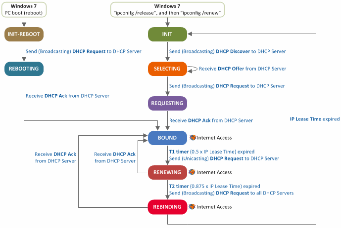
Figure 8. State transition diagram of DHCP clients
- In the INIT state, a client PC broadcasts a DHCP Discover message to search for a DHCP server, and transits to the SELECTING state.
- In the SELECTING state, a client PC will stay in standby, waiting for a DHCP Offer message. Upon receiving multiple DHCP Offer messages, the client PC selects one of the messages (i.e., a message received first or one from the DHCP server which has previously allocated an IP address to it), and broadcasts a DHCP Request message including the selected DHCP server information. Then, it transits to the REQEUSTING state.
- In the REQUESTING state, when a client PC receives a DHCP Ack message, it configures T1 and T2 timers according to the IP address lease time specified in the DHCP Ack message, and transits to the BOUND state. Here, the timers T1 and T2 are used to extend the IP address lease time, and can be configured as follows in accordance with the reference [1]:
- T1 timer: 0.5 x IP address lease time (e.g. T1 is set to 30 minutes if the IP address lease time is 1 hour)
- T2 timer: 0.875 x IP address lease time (e.g. T1 is set to 52.5 minutes if the IP address lease time is 1 hour)
- In the BOUND state, a client PC checks whether or not the IP address allocated by a DHCP server is in use on the same subnet (Refer to the procedure for detecting IP address conflicts), and configures the network environment according to the information included in the DHCP Ack message. Now, the client PC is connected to the Internet. Later, if T1 timer is expired while the client PC is in the BOUND state, the client PC unicasts a DHCP Request message for renewal of its IP address and then transits to the RENEWING state.
- In the RENEWING state, if the client PC receives a DHCP Ack message that includes network configuration data from a DHCP server (and thus permitted to extend the IP address lease time), it resets T1 and T2 timers and transits to the BOUND state. If it gets no response from a server, it stays in standby, waiting for a DHCP Ack message, until T2 timer is expired, and then transits to the REBINDING state. In the RENEWING state, a client PC can stay online during the lease time even when it has not received any DHCP Ack message from DHCP server(s).
- In the REBINDING state, a client PC broadcasts a DHCP Request message on the subnet so that all of DHCP servers can receive the message. In this state, if the client PC receives a DHCP Ack message from a DHCP server, it resets T1 and T2 timers and transits back to the BOUND state. However, if it receives no response message from DHCP server(s), it transits to the INIT state. In the REBINDING state, the client PC can stay online until it transits to the INIT state even when it has not received any DHCP Ack message from DHCP server(s).
- INIT-REBOOT state stands for the state when a client PC is already aware of an IP address to be allocated, and a client PC (Windows 7) transits to this state when it is rebooted. In this state, a client PC broadcasts a DHCP Request message and then transits to the REBOOTING state.

- In the REBOOTING state, upon receiving a DHCP Ack message, a client PC sets T1 and T2 timers according to the IP address lease time specified in the DHCP Ack message, and then transits to the BOUND state.
References
[1] R, Droms, “Dynamic Host Configuration Protocol”, RFC 2131, Standard, March 1997.
[2] W, Wimer, “Clarifications and Extensions for the Bootstrap Protocol”, RFC 1542, Standard, October 1993.
[3] Netmanias Technical Document, “Understanding the Basic Operations of DHCP”, October 2013, https://www.netmanias.com/en/?m=view&id=techdocs&no=5998
[4] Bits&Pieces, http://www.kimiushida.com/bitsandpieces/articles/packet_analysis_dhcp/index.html
Excellent write up, Great and Thank you
Helpfull insight, thank you very much.
Great Article,
Point to note is that , all messages will be broadcasted unless there is a last allocated IP in client's registry , which is not the case for first reboot or loss or last allocated IP.
Great Write Up. You guys have a great format that makes it easy to follow and understand. Keep up the great work.
Perfect!!